Each switch, three states
No fault · Open circuit · Contact resistance or short circuit. With 22 switches, this results in significantly more fault scenarios than the number would suggest.
Original components ranging from the ignition system to the complete exhaust system, measuring sockets in the circuit diagram colors attached directly to the components—and 22 fault switches, each with a documented solution.
The breakout box is connected directly to the control unit; the wires run through test sockets there, many of them through 4 mm bridge plugs. The components carry pin-outs. You measure the signal at the control unit and at the component, open the line and test it – and measure current right in the panel. That is full diagnostics.
Fault in the wire, connector, component – or the control unit?
1 · At the control unit: 4.8 V – the control unit delivers.2 · Fault switched on – at the component pin-out: 0 V.3 · Bridge plug pulled, box ↔ pin-out tested: wire open.4 · Ammeter instead of bridge plug: current right in the panel.
The breakout box sits directly at the control unit: here you see the signal it outputs – e.g. 4.8 V.
Measure at the component pin-out. If 0 V arrives there, the fault is between box and component.
Pull the 4 mm bridge plug and test the wire from box to pin-out with an ohmmeter: open – fault located.
Where a wire runs through a bridge plug, an ammeter simply replaces the plug.
Parallel tapping systems are simpler to build – and cheaper. But they only show that a fault exists, not where. Only a breakout box at the control unit plus pin-outs at the component enables full diagnostics – voltage, continuity and current on every wire with a bridge plug.
Four points where the TSI Training Engine differs from a diagram — you measure on the trainer, not on the drawing.
No fault · Open circuit · Contact resistance or short circuit. With 22 switches, this results in significantly more fault scenarios than the number would suggest.
About 80 measuring sockets are located directly on the components, color-coded to match the original schematic. There is also a measuring socket panel that allows you to individually create open circuits for occupied control unit pins.
Instrument cluster, ignition switch, and speed simulation in the control panel; catalytic converter with a connection for exhaust emission testers. Rotating and hot parts are protected.
With TPGO, the courses are also compatible with your existing THEPRA devices—your existing equipment remains in use. Anyone who purchases a 4.0 device with TPGO today will also be able to use it with the older trainers in their facility.
… and 14 more tasks. The complete list is in the manual.
| Voltage | 12-V Vehicle Battery |
|---|---|
| Learning units | 22 Fault Circuits |
| Handbook | Theory · Tasks · Solutions |
| E-Learning | Optional |
| Engine (reference) | 1.4 TSI · CAXA · 1390 cm³ · Euro 5 |
|---|---|
| Dimensions (L × W × H) | 1690 × 880 × 1520 mm |
| Weight | approx. 310 kg |
| Power supply | 12-V Vehicle Battery |
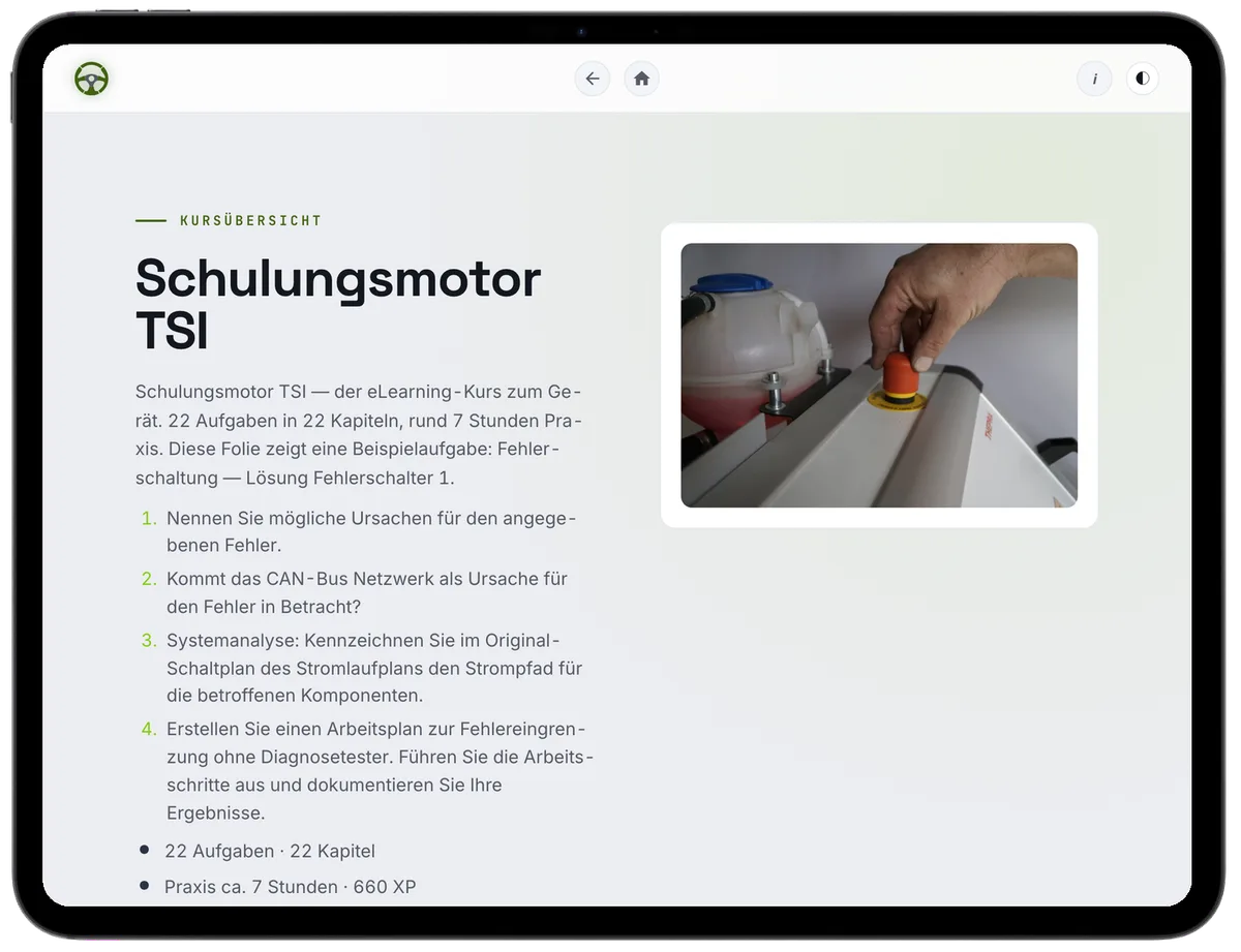
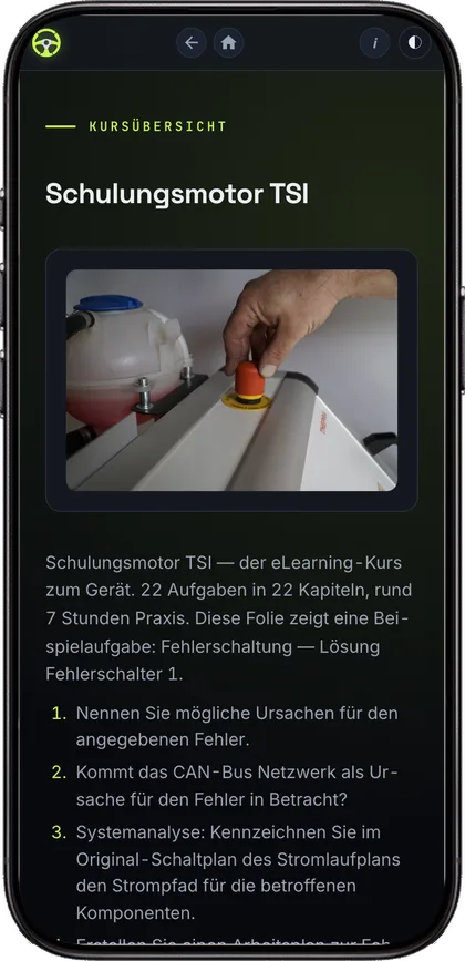
The TSI Training Engine comes with a complete course on TPGO. It runs in the browser — tablet, phone, computer. The tasks walk through the same measurements the apprentice takes on the trainer: first the assumption, then the series of readings, then the comparison.
Fundamentals 100 % · Advanced 0 % SOLO 3–3 · Apply Bloom · EQF 2–2
Certificate · Progress & XP
License for an unlimited number of students and teachers · Term: 10 years, renewable · Activation on your TPGO E-Learning domain.
Request now arrow_forwardA demonstration takes about two hours. We set it up, show the tasks on the trainer and the course that goes with it. You will see right away whether it fits your training workshop.