True voltage, reduced current
The high voltage measuring sockets carry the actual voltage, but the current is significantly reduced. The measurement is based on the actual value—without putting the production vehicle at risk.

38 hidden, switchable faults in the powertrain, charging system, and vehicle electrical system; test points located behind a lockable protective cover—plus the test reports for insulation resistance and equipotential bonding.
The breakout box is connected directly to the control unit; the wires run through test sockets there, many of them through 4 mm bridge plugs. The components carry pin-outs. You measure the signal at the control unit and at the component, open the line and test it – and measure current right in the panel. That is full diagnostics.
Fault in the wire, connector, component – or the control unit?
1 · At the control unit: 4.8 V – the control unit delivers.2 · Fault switched on – at the component pin-out: 0 V.3 · Bridge plug pulled, box ↔ pin-out tested: wire open.4 · Ammeter instead of bridge plug: current right in the panel.
The breakout box sits directly at the control unit: here you see the signal it outputs – e.g. 4.8 V.
Measure at the component pin-out. If 0 V arrives there, the fault is between box and component.
Pull the 4 mm bridge plug and test the wire from box to pin-out with an ohmmeter: open – fault located.
Where a wire runs through a bridge plug, an ammeter simply replaces the plug.
Parallel tapping systems are simpler to build – and cheaper. But they only show that a fault exists, not where. Only a breakout box at the control unit plus pin-outs at the component enables full diagnostics – voltage, continuity and current on every wire with a bridge plug.
Four points where the Training Vehicle All-electric (e-up!) differs from a diagram — you measure on the trainer, not on the drawing.
The high voltage measuring sockets carry the actual voltage, but the current is significantly reduced. The measurement is based on the actual value—without putting the production vehicle at risk.
Insulation resistance and equipotential bonding as documented test reports—the documentation required for work on high voltage systems. Testing for faults with a connected charger is also a separate task.
The high voltage measurement points are located behind a lockable, transparent protective cover: visible for instructional purposes, but accessible only upon the trainer’s approval.
With TPGO, the courses are also compatible with your existing THEPRA devices—your current equipment remains in use. Anyone who purchases a 4.0 device with TPGO today will also be able to use the older trainers in their facility.
… and 32 more tasks. The complete list is in the manual.
| Learning units | 40 exercises · 38 faults |
|---|---|
| Handbook | 190 pages · Theory · Tasks · Solutions |
| E-Learning | Optional |
| Dimensions (L × W × H) | 3540 × 1645 × 1481 mm |
|---|---|
| Drive | Three-phase motor 60 kW · 210 Nm |
| High-voltage battery | 374 V · 50 Ah · 18.7 kWh |
| Weight | 1150 kg |
| Conformity | CE · UKCA · RoHS |
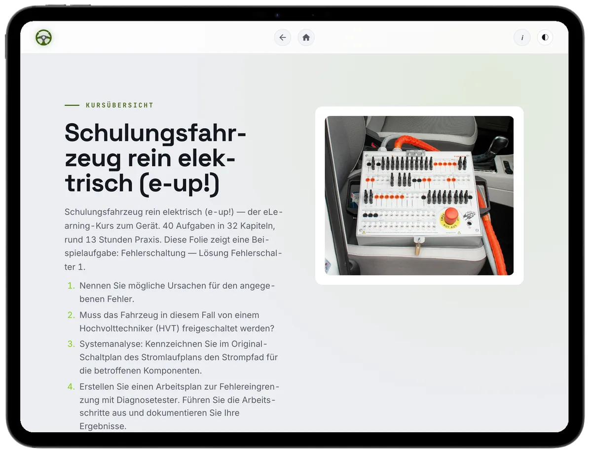
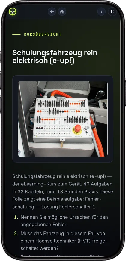
The Training Vehicle All-electric (e-up!) comes with a complete course on TPGO. It runs in the browser — tablet, phone, computer. The tasks walk through the same measurements the apprentice takes on the trainer: first the assumption, then the series of readings, then the comparison.
Fundamentals 100 % · Advanced 0 % SOLO 3–3 · Apply Bloom · EQF 2–2
Certificate · Progress & XP
License for an unlimited number of students and teachers · Term: 10 years, renewable · Activation on your TPGO E-Learning domain.
Request now arrow_forwardA demonstration takes about two hours. We set it up, show the tasks on the trainer and the course that goes with it. You will see right away whether it fits your training workshop.