De-energize
and re-energize.
Treat both procedures as separate tasks—because the process of re-energizing is often skipped during training, yet it is just as subject to regulations in the workplace as the process of de-energizing.
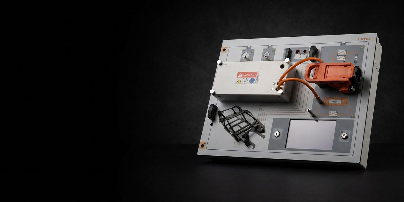
Original manual service disconnect connector, functional pilot line, Inverter with a screw-on metal cover, HV capacitor for discharging — the complete procedure on the actual component. The trainer operates at a limited current: the procedures are real, the current stays below 5 mA. The following are tested: Inverter, traction motor, high-voltage battery, and AC compressor — using real workshop measurement equipment, at either 40 V or 202 V. Training follows workshop practice: under the supervision of competent staff and with PPE as specified in the work instructions. For the inverter test mode, the manual explicitly warns of electric shock.
What the trainer does in class — shown in a minute, with sound. Subtitles can be switched on in the player.
Not a replica: the manual service disconnect is an original and is functionally connected to the pilot line. Pulling it creates an open circuit—and the system reacts just as it would in the vehicle. The Inverter is housed in a metal enclosure with a screw-on cover; behind it is the high-voltage capacitor with its own measurement points.
You shouldn't practice the procedure on the vehicle—it has to be second nature. That's exactly what this trainer is for: the same procedure, as many times as you like, with faults that someone has intentionally introduced.
Treat both procedures as separate tasks—because the process of re-energizing is often skipped during training, yet it is just as subject to regulations in the workplace as the process of de-energizing.
The device displays the voltage of a real vehicle system—it outputs 40 V. Trainees read the value they will later see in the vehicle and act accordingly. In the 202 V setting, the voltage is applied as in a real-world scenario, and the current remains below 5 mA. This also allows trainees to practice Task 7: measuring on a system that is still live.
Once the cycle is complete, it's time for troubleshooting: seven error groups, set via the touchscreen and secured against accidental changes using the key switch. The trainee doesn't know what settings have been selected—but the instructor does.
| manual service disconnect | Original · orange · on pilot line |
|---|---|
| Inverter | Metal housing · bolted |
| HV capacitor | Measurement Points T+ / T− |
| HV lines | orange · shielded |
| Touchscreen | 4.7inches |
|---|---|
| Key Switch | Ignition Start + Lock |
| HV Measurement Points | Motor U · V · W · AC compressor |
| Ground points | 5 × |
| Design | 4 mm · Safety design |
| power supply | 10–15V DC |
|---|---|
| Setting 202 V | 202V real · at < 5 mA |
| Setting: 400 V | 40V (real) · 400 V (simulated) |
| Recommended power supply | TS10 · Art. No. 12 050 010 |
| Sound pressure level | < 70dB(A) |
| Dimensions W × D × H | 399 × 297 × 150mm |
|---|---|
| Weight, approx. | 3.6kg |
| form factor | Table · DIN-A4 Support Frame |
| Conformity |    |
It stands at the start of high-voltage training: before anyone works on connectors or cable assemblies, the de-energization procedure has to be second nature.
The first seven modules cover the entire process—from preparation to measuring under voltage. The remaining thirteen modules focus on troubleshooting across seven categories of faults. Includes a digital curriculum and the accompanying E-Learning.
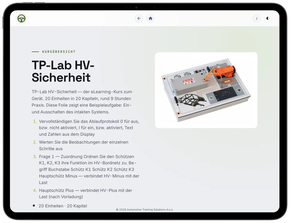
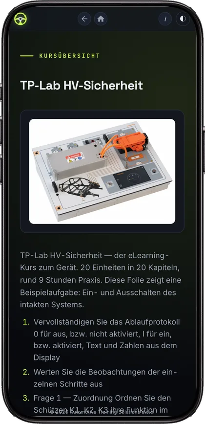
The TP-Lab High-Voltage Safety comes with a complete course on TPGO. It runs in the browser — tablet, phone, computer. The tasks walk through the same measurements the apprentice takes on the trainer: first the assumption, then the series of readings, then the comparison.
Fundamentals 80 % · Advanced 20 % SOLO 3–4 · Bloom's Taxonomy · EQF 2–3
Examples — in total the course is mapped to more than 90 curricula.
Certificate · Progress & XP
License for an unlimited number of students and teachers · Term: 10 years, renewable · Activation on your TPGO E-Learning domain.
Request now arrow_forwardA demonstration lasts about two hours. We'll walk through the entire process of de-energizing once and then simulate a fault for you to troubleshoot.